Read our other blog posts from our “LiDAR technology” serie
 |
LiDAR integration with ROS: quickstart guide and projects ideas
In this post, you will learn how to connect and integrate your LiDAR with your PC or embedded system using ROS middleware on Ubuntu. We will also talk about data fusion (widely used in mobile robotics).
Are you new to ROS?
The Robot Operating System (ROS) is a set of softwares libraries and tools that help you build robot applications. From drivers to state-of-the-art algorithms, and with powerful developer tools, you will almost certainly need ROS for your next robotics project. ROS is completely open source.
If you don’t have Ubuntu set up on your computer, follow this instructions to download the latest version. You have to download ROS distribution matching your Ubuntu version, for the Ubuntu 18.04 version, you need to install ROS Melodic .
Once your computer is running on Ubuntu and that ROS is set up, we recommend you to look up these ROS tutorials to get familiar with this middleware (beginner and intermediate levels available).
Receive data from your LiDAR
In order to connect the LiDAR to you PC, you must first take care of the power supply. Depending of your device, it may require 5VDC or 12/24VDC, for instance.
5VDC supply voltage is usually supported by a USB connector plugged into your PC, you just have to wire it and the LiDAR will be ready to spin.
For higher supply voltage, you need an external alimentation (low frequency generator), a transformator/converter wired to main supply, or a battery.
Once you have connected your LiDAR with its power supply, you need to connect the data transmitter.
It could be through the same cable as USB supplier, with a different one, with a Rx/Tx cable, a UART cable or an Ethernet cable. Usually, an adapter is sold with the LiDAR.
Read data from your LiDAR
Once your LiDAR is ready to be used, you have to check if you have the permissions on data input port:
Once you have connected the data transmitter cable on the USB or Ethernet port, type the following command line to check the permissions:
$ ls -l /dev/tty
You should see a new item labelled ACMX or USBX , X being a figure equal or higher than zero (depending on how many ports are already in-use).
Your output should be in the form:
$ crw-rw-XX- 1 root dialout 166, 0 2016-09-12 14:18 /dev/ttyACM0
or
$ crw-rw-XX- 1 root dialout 166, 0 2016-09-12 14:18 /dev/ttyUSB0
- If XX is rw, then the laser is configured properly.
- If XX is –, then the laser is not configured properly and you need to change permissions like below:
$ sudo chmod a+rw /dev/ttyACM0
or
$ sudo chmod a+rw /dev/ttyUSB0
Once the permissions are configured, you have to download the package of your LiDAR manufacturer:
- Slamtec GitHub
- Slamtec tutorial
- YDLiDAR GitHub
- Hokuyo GitHub
- Hokuyo tutorial
- ROS SICK GitHub
- ROS2 SICK GitHub
- SICK tutorial
- RoboSense GitHub
For downloading LiDAR package from GitHub in the src folder of your ROS environment , the commands are:
$ cd ~/your_workspace/src
$ git clone
(please refer to the manufacturers GitHub links above)
Write down the package name you have just downloaded.
$ cd ..
$ catkin_make
$ source devel/setup.bash
Go in launch folder and find the launch file name which match with your LiDAR version and launch it:
$ roslaunch votre_package votre_launch.launch
To check that the LiDAR is publishing to /scan, use
$ rostopic list
All active topics will be listed, check that /scan is present. Next, check the messages being published to /scan by using:
$ rostopic echo /scan
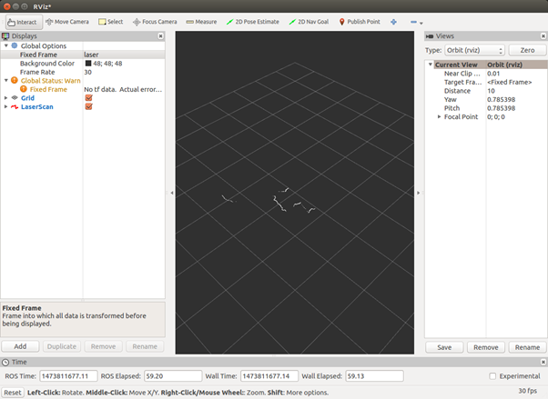
You will be successfully able to stream data from the LiDAR. You can visualize the data on RViz with the command line below. More details about this method here: using ROS to read data from a LiDAR . If you want to learn more about RViz, read this tutorial .
$ rosrun rviz rviz
Click add, then select the topic /scan. If you have an error related to tf, you need to manually enter your fixed frame as “/your_LiDAR_frame_id ” in the textbox next to fixed frame on the left side of the GUI.
The result should be a line mapping distances from the LiDAR in a rectangular coordinate system.
To integrate the LiDAR with another package, you just need to call this launch from your main launch.
Some LiDAR require some additional steps of configuration. The readme file of your manufacturer package should help you with that.
On ROS, all 2D LiDAR will publish data on the topic of LaserScan and PointCloud type for 2D/3D LiDAR. A lot of code samples are available online to help you process this data.
Implementing LiDAR processed data
1) Mapping
LeGO-LOAM
LeGO-LOAM is specifically optimized for a horizontally placed VLP-16 or Robosense LiDAR on a ground vehicle. The LiDAR “postulates” that there is always a ground plane in the scan.
The UGV we are using is The UGV we are using is . It has a built-in IMU.
This repository contains code for a lightweight and ground optimized LiDAR odometry and mapping (LeGO-LOAM) system for ROS compatible UGVs.
The system takes in point cloud from a Velodyne VLP-16 LiDAR (placed horizontal) and optional IMU data as inputs. You can use another 3D LiDAR, like the RS-LIDAR-16 by Robosense, you need to change parameters.
Il fournit une estimation de pose 6D en temps réel.
A demonstration of the system can be found here .
Must be set up:
- ROS (tested with indigo and kinetic)
- GTSAM (Georgia Tech Smoothing and Mapping library, 4.0.0-alpha2)
A-LOAM
A-LOAM (Georgia Tech Smoothing and Mapping library, 4.0.0-alpha2)
This code is modified from LOAM and LOAM_NOTED . This code is clean and simple without any complicated mathematical derivation or redundant operations.
It is a good learning material for SLAM beginners.
Must be set up:
- ROS (Kinetic or Melodic)
- Ceres Solver
- PCL
3D LIDAR-based Graph SLAM
hdl_graph_slam is an open source ROS package for real-time 6DOF SLAM using a 3D LIDAR. It is based on 3D Graph SLAM with NDT scan matching-based odometry estimation and loop detection.
It also supports several graph constraints, such as GPS, IMU acceleration (gravity vector), IMU orientation (magnetic sensor), and floor plane (detected in a point cloud).
We have tested this package with both Velodyne (HDL32e, VLP16) and Robosense (16 channels) sensors, in indoor and outdoor environments.
Spin Hokuyo
This repository contains code to control a Dynamixel servomotor and a 2D Hokuyo LiDAR to create a 3D point cloud that can be visualized in RViz.
This point cloud can then be used to create an octomap.
Wiki Page: http://wiki.ros.org/spin_hokuyo
Here is another 3D scanning project that involves a Hokuyo UTM-30LX LiDAR : 3D photobooth .
2) Calibration
ROS package to calibrate a camera and a LiDAR
This ROS package is used to calibrate a Velodyne LiDAR with a camera (works for both monocular and stereo). Specifically, Point Gray Blackfly and ZED camera have been successfully calibrated against Velodyne VLP-16 using LiDAR_camera_calibration.
is used to calibrate a Velodyne LiDAR with a camera (works for both monocular and stereo). Specifically, Point Gray Blackfly and ZED camera have been successfully calibrated against Velodyne VLP-16 using LiDAR_camera_calibration.
The package finds a rotation and translation that transform all the points in the LiDAR frame to the (monocular) camera frame.
The package uses aruco_ros and a slightly modified aruco_mapping as dependencies, both of which are available in the dependencies folder in this repository.
The package uses aruco_ros and a slightly modified aruco_mapping as dependencies, both of which are available in the dependencies folder in this repository.
A paper was written about this project, you can read it here .
3) Tracking
Multiple object tracking with LiDAR
Le PCL based ROS package to Detect/Cluster –> Track –> Classify static and dynamic objects in real-time from LIDAR scans implemented in C++.
Features:
- K-D tree-based point cloud processing for object feature detection from point clouds
- Unsupervised k-means clustering based on detected features and refinement using RANSAC
- Stable tracking (object ID & data association) with an ensemble of Kalman Filters
- Robust compared to k-means clustering with mean-flow tracking
4) Fusion
Extended Kalman Filter Project Starter Code
Self-Driving Car Engineer Nanodegree Program. In this project , you will use a kalman filter to estimate the state of a moving object of interest with noisy LiDAR and radar measurements.
Passing the project requires obtaining RMSE values that are lower than the tolerance outlined in the project rubric.
This project involves the Term 2 Simulator which can be downloaded here .
This repository includes two files that can be used to set up and install uWebSocketIO for either Linux or Mac systems. For windows you can use either Docker, VMware, or even Windows 10 Bash on Ubuntu to install uWebSocketIO.
This is an extended Kalman Filter implementation for fusing LiDAR and radar sensor measurements. A Kalman filter can be used where information about some dynamic system are uncertain, so your best bet is to do some educated guesses about what the system is going to do next.
In this case, we have two ‘noisy’ sensors:
- A LiDAR sensor that measures our position in cartesian-coordinates (x, y)
- A radar sensor that measures our position and velocity in polar coordinates (rho, phi, drho)
We want to predict our position, and how fast we are going in what direction at any point in time:
- In essence: the position and velocity of the system in cartesian coordinates: (x, y, vx, vy)
- Note that we are assuming a constant velocity model (CV) for this particular system
UKF Fusion
Compared to the Extended Kalman Filter with a constant velocity model, RMSE should be lower for the unscented Kalman filter especially for velocity.
The CTRV model is more precise than a constant velocity model. And UKF is also known for handling non-linear equations better than EKF.
Using a LiDAR is sometimes not enough for some applications. Indeed, other data must be collected to ensure accuracy. As the sensor is moving (if it’s part of a mobile robot ), location and orientation of the device must be included to determine the position of the laser pulse at the time of sending and the time of return.
This extra information is crucial to the data’s integrity. Common additional sensors are:
- A camera
- A GPS chip
- A IMU (Inertial Measurement Unit)
- ToF sensors
To get accurate values your need to merge those data and keep the ones most trusted depending of the environment and the situation. This step is called data fusion. Sometimes the sensors are giving the same kind of data but with different values due to their accuracy and error.
It is very important to find the real value based on sensors’ different values.
The data fusion is a crucial step. Merging all those data would able the robot to locate itself in its known environment. The higher the sensor accuracy and the navigation software accuracy are, the higher the estimated position will be.
SLAM implementation in mobile robotics
The most famous SLAM algorithms are:
The following diagram shows the architecture of the navigation stack of ROS which implements a SLAM algorithm:
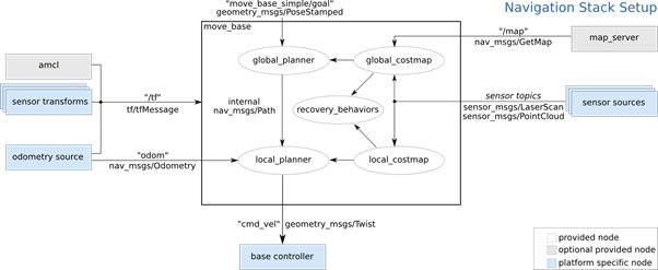
Sensors are providing the input values: sensor sources and odometry source. Based on those two data sources, the algorithm calculates the sensor transformation, the pose estimate (amcl) and map the environment (map_server). Thanks to all this data, the path planner can take decisions.
Sensors are essential, and the LiDAR is the best sensor to get LaserScan or PointCloud data.
You can read an in-depth publication about SLAM algorithm in this introduction to navigation with ROS .
Read our other blog posts from our “LiDAR technology” serie
| |
Do not hesitate to browse our LiDAR selection or to contact us if you need additional information or a quotation.
LiDAR distributed by Génération Robots
 |
|
|
| |
|
|