This Arduino based project tutorial was created by an amateur and is mainly aimed at other amateurs, or anyone with a bit of curiosity for this type of electronic DIY projects.
The author appeals in advance to the benevolence of the venerable experts whom would like to dig a little in the code or in the mechanical conception (Arduino code and STL files available at the end of this article).
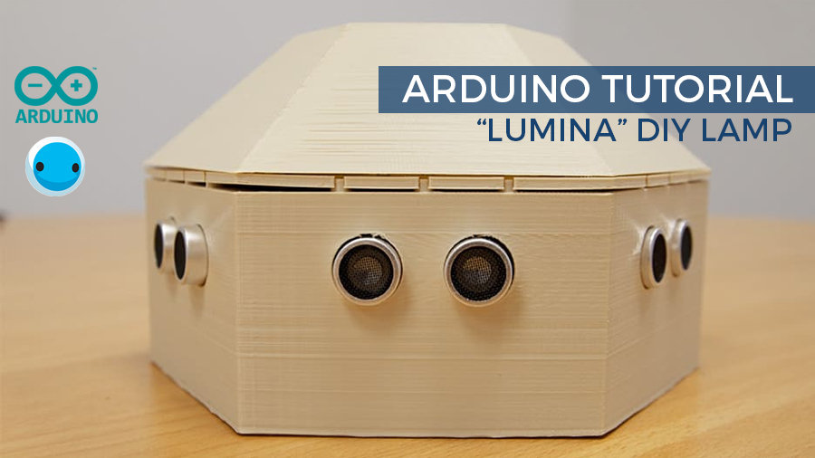
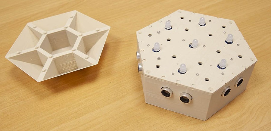
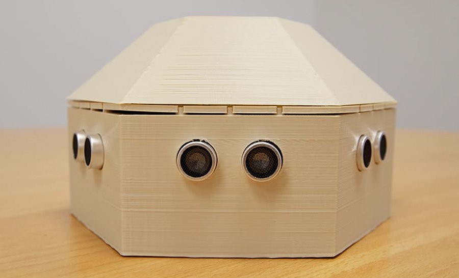
LUMINA is a 3D-printed lamp, based on RGB LEDs whose color and intensity can be modified. It features different modes , and can be used as a decorative lamp or as a game. The user interacts with the lamp’s 6 ultrasonic sensors to switch between the different modes or activate the LEDs.
What hardware do you need?
- 1 x Arduino Uno Rev3 main board .
- 1 x USB Cable B type.
- 1 x piezoelectric buzzer (optional).
- 1 x 220 ohms resistor.
- 1 x 400 points breadboard.
- M/M and M/F Jumper cables (all the components are available in the Official Starter Kit Arduino).
- 6 x HC-SR04 ultrasonic sensors.
- 7 x chainable RGB Grove LED v2.
- 2 x pack of 5 5cm cables.
- A little less than 300g of filament (130g for the base, 65g for the plate and 75g for the lid). In my case, I used ivory white colored Chromatik filament
- M2 6mm bolts and M2 nuts , or double-sided tape.
- Recommended: 1 pack of 5 Grove male jumper cable.
- Optional: 1 x mural charger (compact USB charger 5V or a 7-12V power adapter, for example this one). If not, connect the USB cable to a computer port.
Software and libraries to download
Assemble your LUMINA lamp
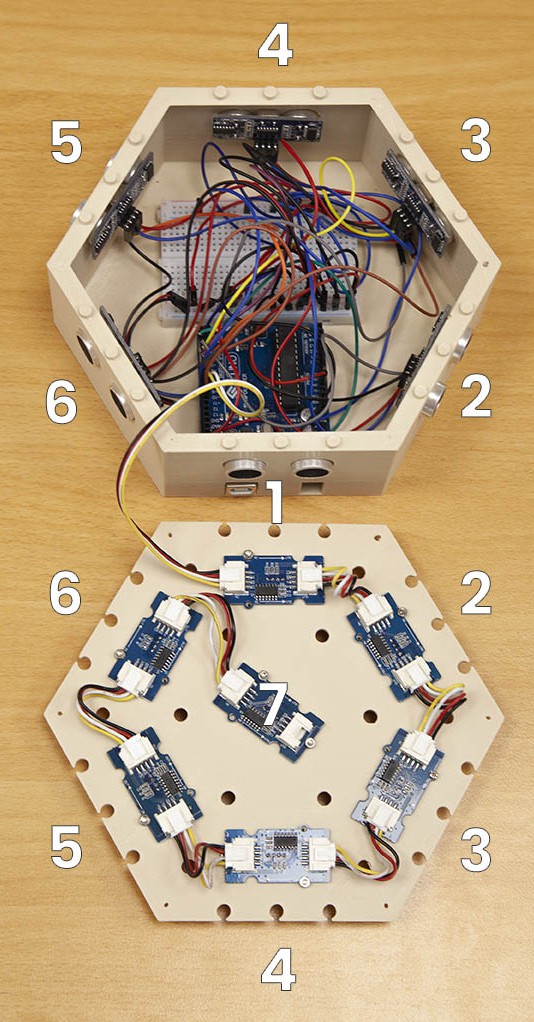
Place the Arduino board inside the case, as close as possible of the inside panel. Afterwards, attach the breadboard with the double-sided tape on the underside, so that the Arduino cannot move.

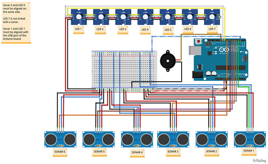
Connect the ultrasonic sensors and the buzzer according to the Fritzing diagram . When the sonar 1 is integrated into the case, it must be placed above the Arduino’s USB and jack connectors.
Attach the Grove LED modules to the underside of the intermediate plate. If you prefer using some double-sided tape than screwing the modules, base yourself on the position of the bolts passages, so as to orient the LEDs correctly.
Connect the “IN” of the central LED (number 7) to the “OUT” of one of the peripheral LEDs. Then, connect the peripheral LEDs one by one, using the 5cm Grove cables. You can pull them off, for more flexibility.
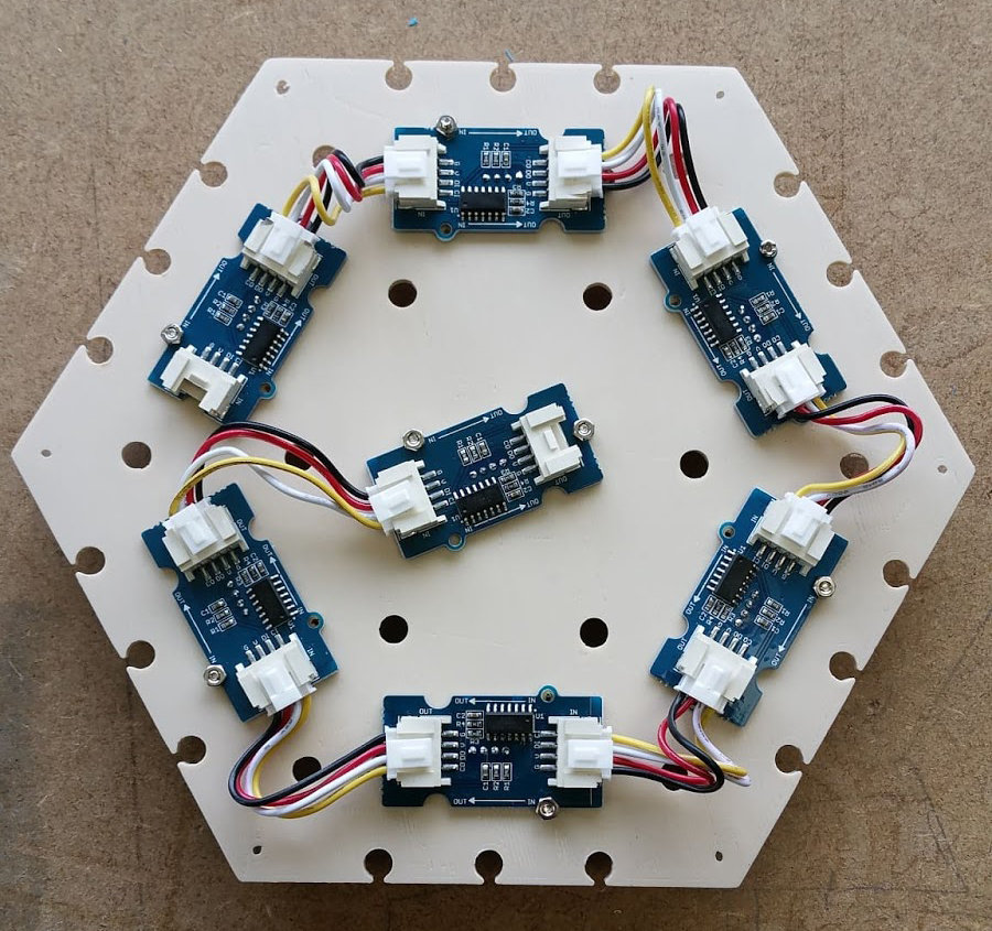
The “IN” of the last LED (number 1) must be connected to the Arduino (signal) on one side and to the breadboard (5V and ground) on the other side with a mixed Grove – jumper male cable.
Close the box with the intermediate plate. The LED 1 (the one directly connected to the Arduino) must be above the sonar 1 (above the Arduino connectors).
Before closing the lid, I recommend you to test your lamp. Just upload the code onto your Arduino board (you can download the code from our resources section, at the bottom of this page).
OPTIONAL: screw the plate into the box (maybe you plan to have the lamp handled by children and need everything to be fastened). Be cautious, as the ultrasonic sensors can be pushed into the case, with a simple pressure (and this can prevent the lamp working correctly). If you wish to screw the plate, you will need to find a way to fasten the sensors. I am currently working on a solution!
Position the lid . Normally, all parts should fit comfortably! You can now power your lamp (USB or jack ports) and start using LUMINA!
How does LUMINA work?
To date, LUMINA lets you switch between 4 operation modes and one selection mode.
Mode 1: manual variation
Three ultrasonic sensors will increase the value of the red, blue and green components in stages , and the other three will decrease these same values . The change is applied uniformly to all the LEDs. A subroutine is used to modify the value of the threshold, in order to accelerate the color changes. Accessible by keeping the sonar 2 and 5* activated at the same time.
Mode 2: automatic variation
Together, the LEDs scan the color spectrum . This is one of the demo codes of the library I used. A subroutine has been added to allow a variation of the scan speed. Accessible by keeping sonar 2 and 5* activated at the same time.
Mode 3: luminous piano
Each sonar is associated with the LED above it, itself associated with a color. Activating a sonar turns on the corresponding LED with its matching color. When the sonar is no longer active, the LED gradually dims until it fade out.
Several LEDs can be lit at the same time. The top LED lights up in white and has its intensity aligned with the last LED activated. Each sonar is also associated with a musical note, played by the buzzer as long as the LED is on. A subroutine allows the duration of the gradient speed to be varied from the moment the sonar is released (between approximately 0 and 5 seconds). Accessible by keeping sonar 2 and 5* activated at the same time.
Mode 4: Simon: the famous game.
The lamp plays a sequence of LEDs accompanied by musical notes, which the player must play again by activating the correct sonars. The game starts with a sequence of 3, incremented at each success, up to a sequence of 10. A success triggers a small green animation, and the next level. A success at the level 10 ends the game. A failure triggers a little red animation and plays back the sequence in progress. The third failure expels the player from the game. The player is subjected to a timer to play his sequence. At the end of the timer, the player is eliminated. In all these cases, the lamp switches back to Mode 2 – automatic variation.
Accessible from all modes except Simon, by keeping sonars 1 and 4* activated. LEDs 1 to 4* light up in white and vary in intensity. Extended activation of one of these sonars will activate the corresponding mode. LEDs 5 and 6* send the player into automatic variation mode. Likewise when the timer expires.
*number according to photos and Fritzing diagram, not according to code.
Genesis of the LUMINA project
The idea to create this lamp came up to me while watching videos of the Bare Conductive kits (especially the capacitive sensor controlled lamps). I already own a 3D printer, and I had noticed that sufficiently thin prints could give a nice transparency effects, that could be use for a project that involves lights.
I lacked knowledge in electronics, but the prospect of being able to complete a DIY project by myself, thanks to 3D printing, was a powerful motivational source!
The choice of platforms
The microcontroller
Having just started programming in Arduino a few months ago, I own the famous Uno R3 for beginner . Hence, the obvious choice for me was to use this board and code on the Arduino IDE!
This being said, it would be possible to use any other board in the Arduino family , or even any other microcontroller ( Raspberry Pi , for those who like to code in Python , for example).
However to those who would like to reproduce the project with a micro:bit, be careful: even if it is possible to have enough pins thanks to the addition of a breakout, the board delivers a voltage of 3.3V, not enough power to supply to make sensors work together.
The sensors
I would have loved using capacitive conductive paint sensors, but they need to be big enough to be effective. I didn’t want the lamp to be to big, and needed a more compact solution. The HC-SR04 ultrasonic sensors are interesting though, as they are both inexpensive and they have a wide detection range. Infrared sensors, such as the Pololu sensors, can work as well.
LEDs
I hesitated for a while with Neopixel RGB LEDs, but Grove chainable LEDs offers the significant advantage of a connection without soldering . Plus they have holes so that can be fasten more easily to any frame. Both references have ready-made Arduino libraries .
The 3D printer
Personally, I used my faithful Neva 3D printer (from Dagoma). For the settings, I chose 0.2mm and with a fast speed, which is more than enough to allows to render a very satisfactory result . All parts fit together! I used an ivory coloured filament (the one I usually choose for my prototypes). The panel are thin, giving to the ensemble a nice diffusion glow, while absorbing the excess of brightness.
NB: The box dimensions fit perfectly on the Neva’s printing surface. Be careful to immediately remove the small piece that the Neva printer at the beginning, before the nozzle passes over it again.
Software tools
The program has been coded in the Arduino IDE. A small tip I share with you: use the NewPing library for the ultrasonic sensors. The HC-SR04 are all connected to the same pin for the trigger, and this caused malfunctions with the “basic” Ping library. Note that the MakeBlock software “mBlock” allows you to program Arduino boards in programming visual language.
I used Tinkercad to design the different box parts. Tinkercad is a free and user friendly online interface . You design the parts by adding and subtracting more or less complex geometric shapes. It is possible to create very elaborate shapess. There are many online video tutorials.
A few tips
As a beginner, there is something exhilarating about your first electronic project. On the other hand, it can also be the source of frustration, faced with unexpected complications or incomprehensible bugs. Here are some suggestions which I hope will help my novice comrades not to fall into discouragement.
Have a clear idea of what you want to do:
As in any creative process, one of the main dangers is to get lost along the way, there is so much possibilities! Keep the final objective clearly in mind during every step of your project s!
Start small:
Rome wasn’t built in a day! If you’re just starting out, don’t start too big. It’s ok if you don’t create a killer invention on your first try! Don’t worry: your friends are beginners just like you, and even a simple DIY project based on obstacle detection and flashing LED should be enough to dazzle them and have them in awe of your new programming skills! Plus, you can always improve your invention as your knowledge grows!
Find a code name for your project:
Because it’s cool. I confess, LUMINA may not win the prize of originality, but if you have several projects at the same time, having a small name for each one will help you find your way around.
Invest in pencil and paper:
Each time I had a new idea and wanted to go type right away a piece of code in the programming interface, I got lost for hours because I didn’t plan out the code instructions ahead.
So, before you throw yourself on your keyboard, take a deep breath, sharpen your pencil and eraser, and… think. “
Whatever is well conceived is clearly said, And the words to say it flow with ease.
” Nicolas Boileau’s quote also applies to programming! You’ll see, pencil and paper are a real time saver!
Go to an info scavenger hunt!
Working with geeks makes it easier when you decide to have a go at an electronic and programming DIY project! They can help you when you run into difficulties! If you don’t have any geeks in your acquaintances, don’t panic! The internet is a wonderful thing if you need to get help on this kind of project! Manufacturers websites , whether it’s Arduino, Raspberry Pi, Python, micro:bit, gives out a lot of useful info… And also, a simple Google with a few well-chosen keywords will get you back on track!
Back to the basics:
Many errors in programming come from silly syntax errors, if though you read your code multiple times! A classic: the notation “if a=0”, where we should write “ if a==0 ”. Enough to drive you crazy. If there is a bug in your program, check even the most elementary syntaxes and instructions.
Comply with programming conventions
Because you may not be the only one reading your code, or simply because you will sometimes need to come back to it after several weeks: follow the good practices in terms of presentation (indentation, my love!) and don’t forget to comment! Again, you will save time and comfort!
Have fun!
If you are interested in this tutorial, then you’re probably an amateur programmer. Learning how to code is exciting, but can also have some daunting and limiting aspects. So, in order to avoid being discouraged, always make sure you do something you like!
Resources of the Arduino tutorial – Creating a DIY lamp “LUMINA”
- STL files for the box: case, fixing plate, lid
- Arduino code. It’s heavy. It’s clumsy. It’s not necessarily very well indented, nor very well commented. But it works! Improvements are welcome!